
DANGER ELECTRICAL SHOCK
Pinball machines have high voltages which can cause DANGER TO LIFE AND LIMB. TURN POWER OFF and UNPLUG PINBALL MACHINE prior to installation. Pinball machines are high voltage and can cause electrical shock.
SAFETY GLASSES are also recommended while working with or installing pinball parts.
Please follow these safety instructions as well as all installation instructions. Failure to follow these instructions may result in damage to the pinball machine, accessory or other parts. Please see our Disclaimer for associated risks and responsibilities (Section 13 in our Terms of Service) prior to installation.
Images included in these instructions are of an installed prototype and may vary from your product slightly.
If you have questions or concerns regarding the proper installation of this part, please contact us for assistance.
When removing screws from the playfield, reinstall by first turning them counter-clockwise to match the original groove in order to respect the integrity of the playfield wood.
***NOTE*** our demonstration model is a prototype and may vary slightly from the production model that you've received. Please take this into account if you see something that is not completely alike what you have received. The instructions will apply the same.
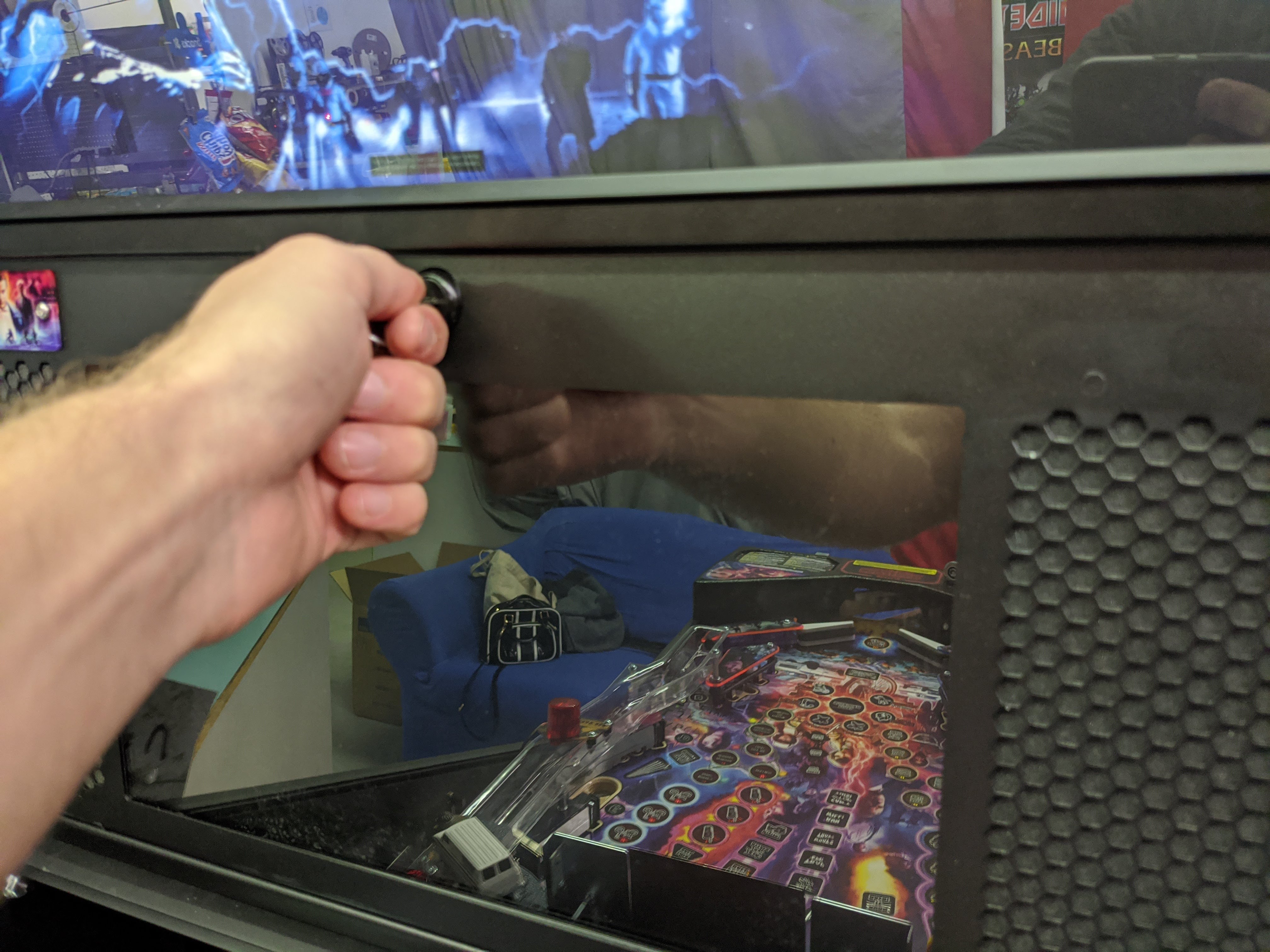
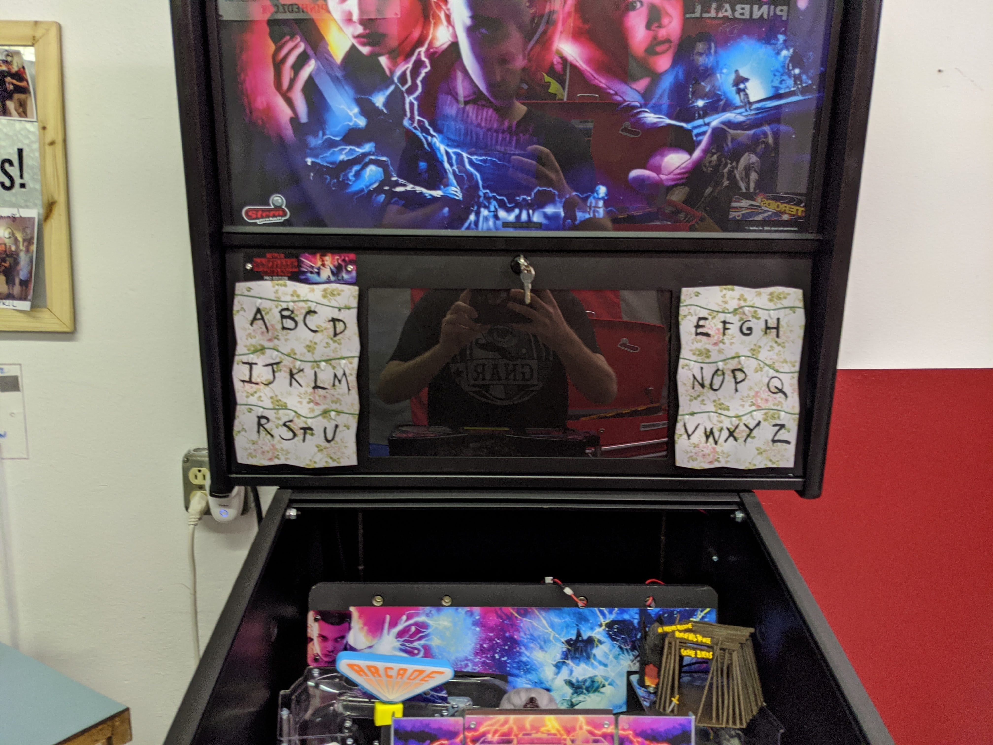
1. Open up the backbox
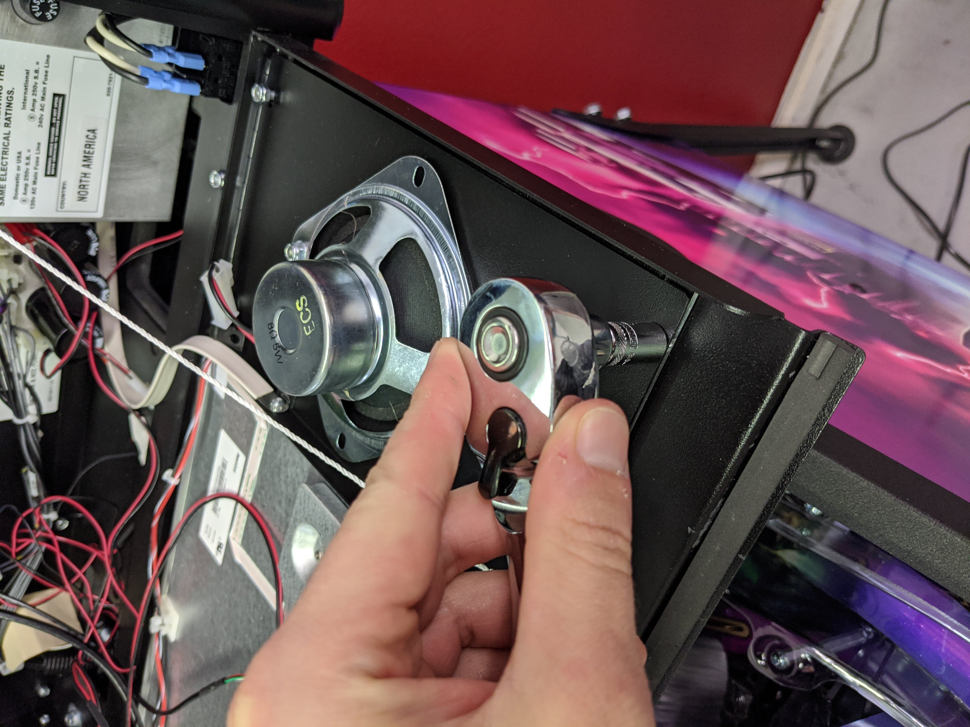
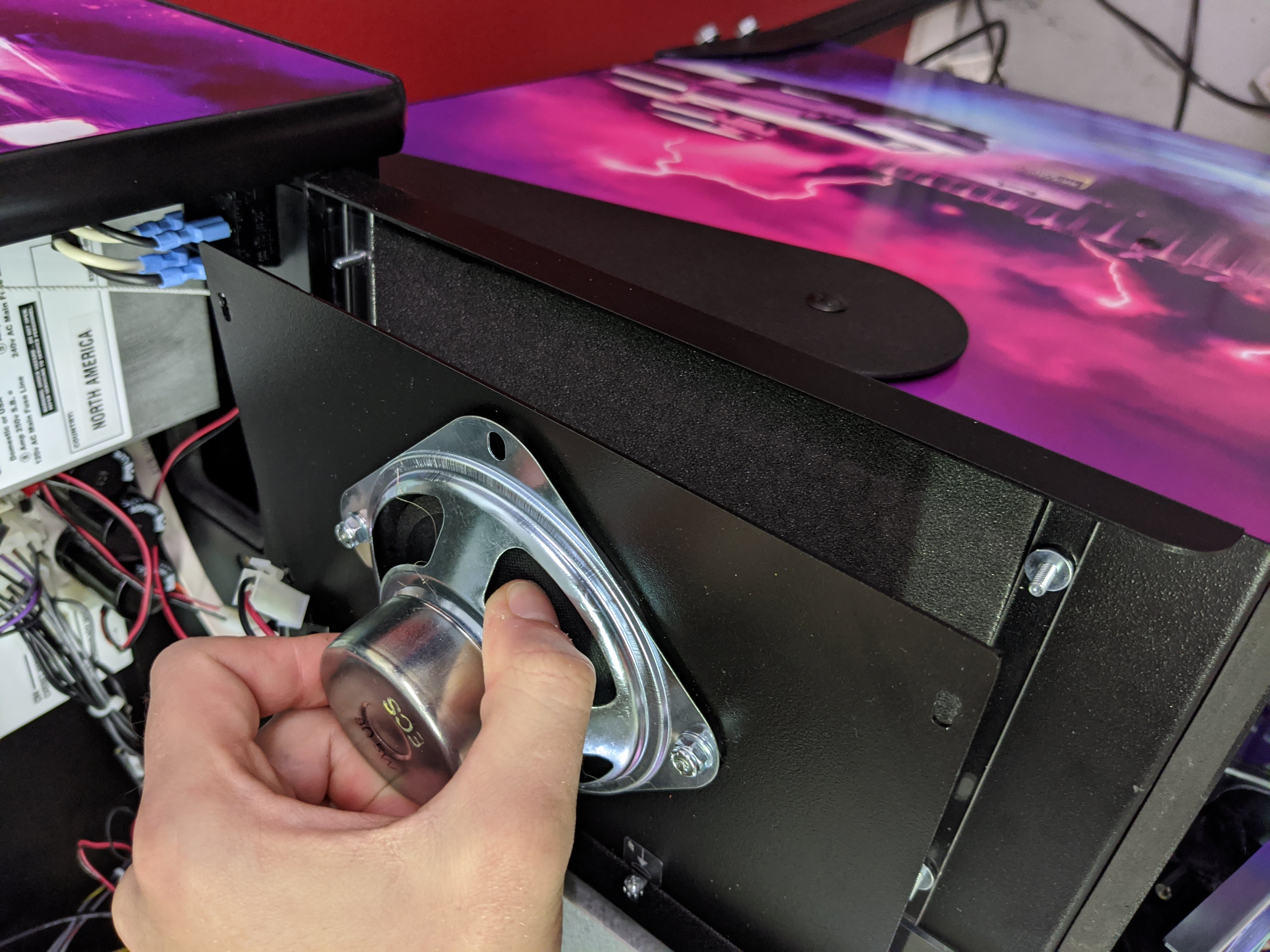
2. Remove the four nuts holding the speaker in place
Using a socket driver, remove the four nuts that are holding the speaker in place. Store these nuts for re installation in a safe place.
3. Gently lift up the speaker assembly to expose the foam sheet below it
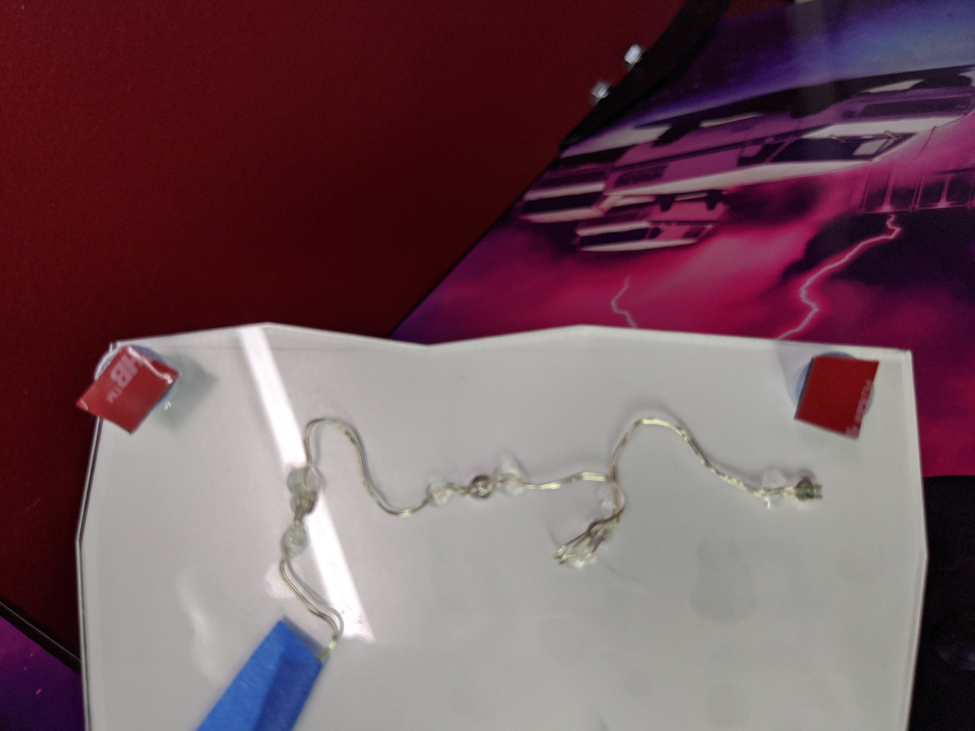
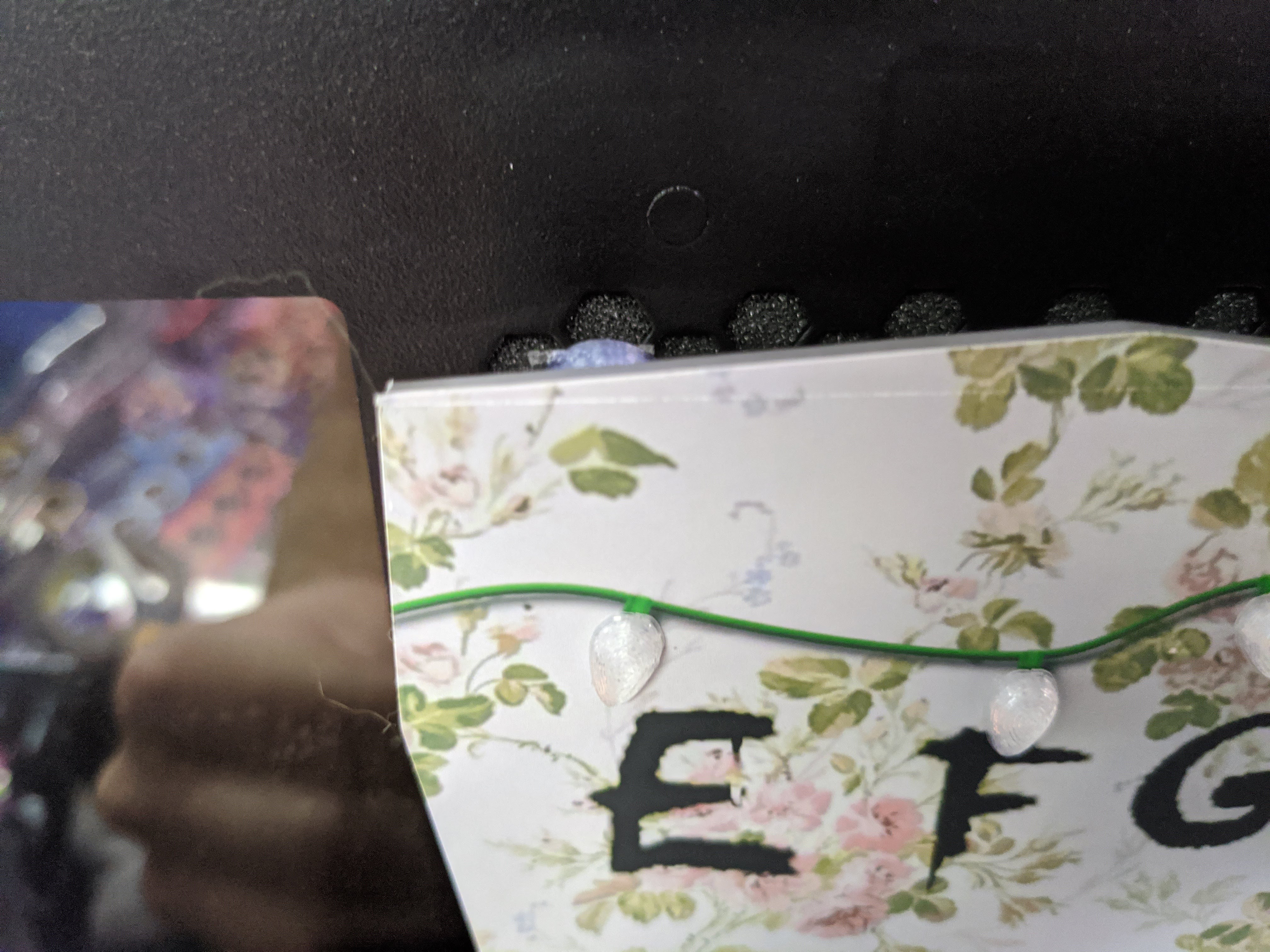
4. Take the right panel (EFG... side) and slip the power wires through the hole in the grate approximately 5 holes from the bottom
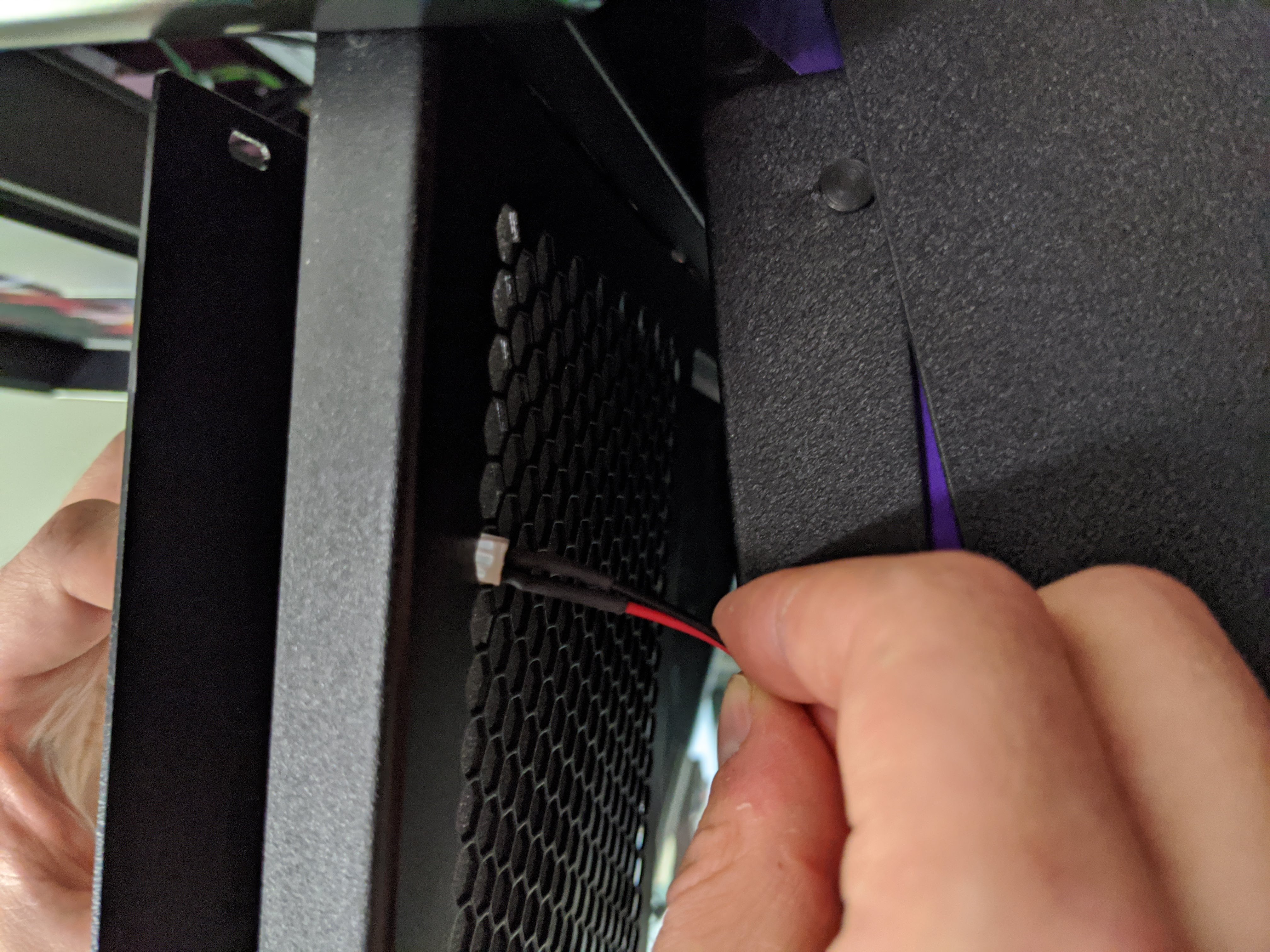
5. Gently pull the slack through the hole until the ABC panel is hanging just below the grate. Pull the power cable off to the side like shown in the photo.
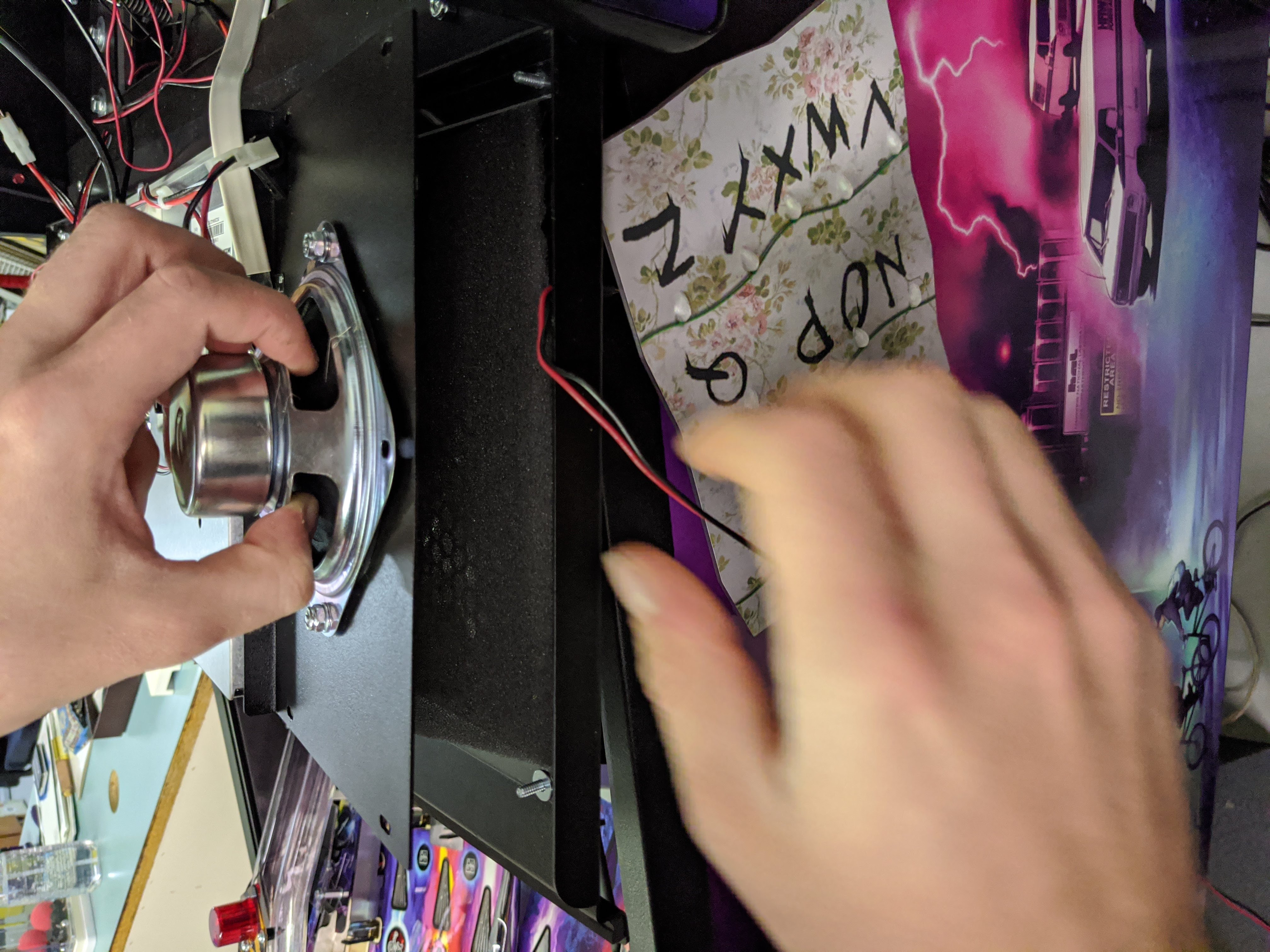
6. Replace the foam and fasten the nuts back into place while ensuring that the sign does not slip downwards.
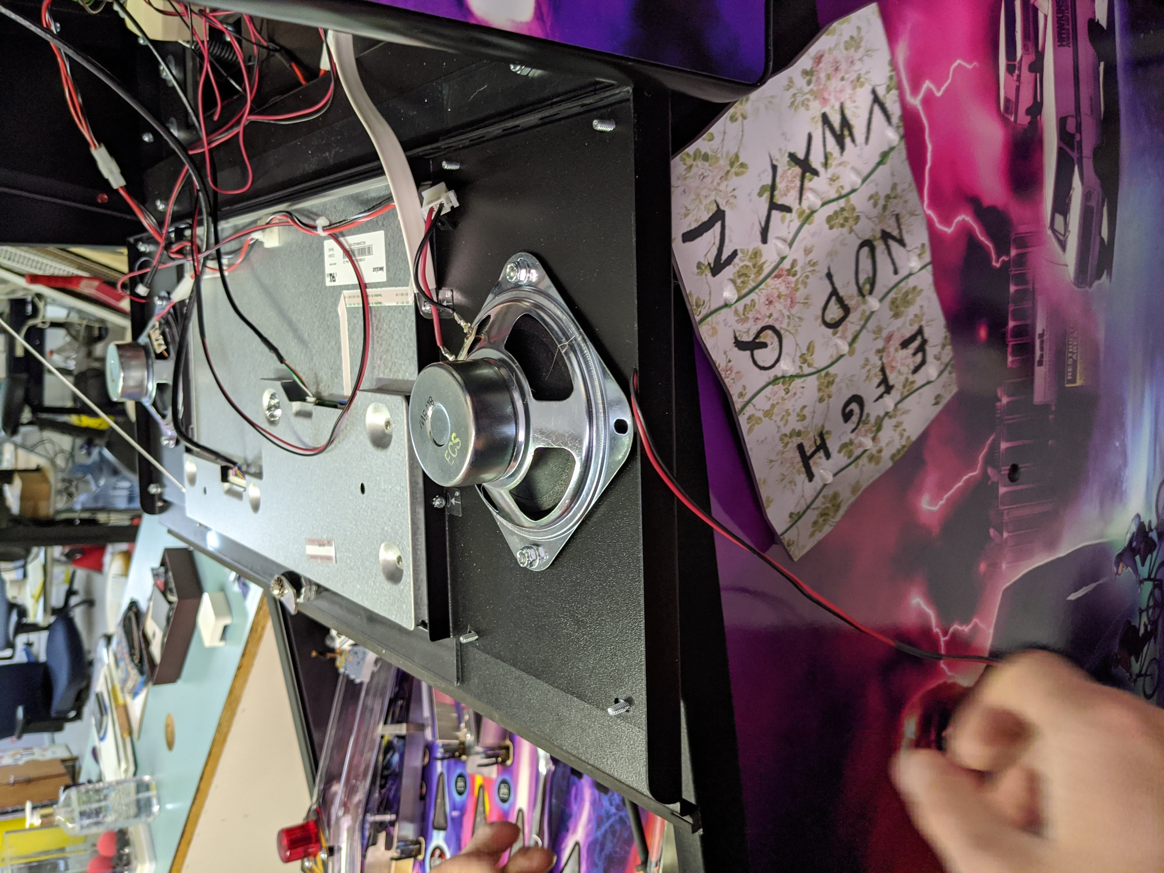
7. Repeat steps 2-6 with the opposite side speaker panel.
8. Connect the two ABC panel power wires together using the included 2-way matrix splitter.
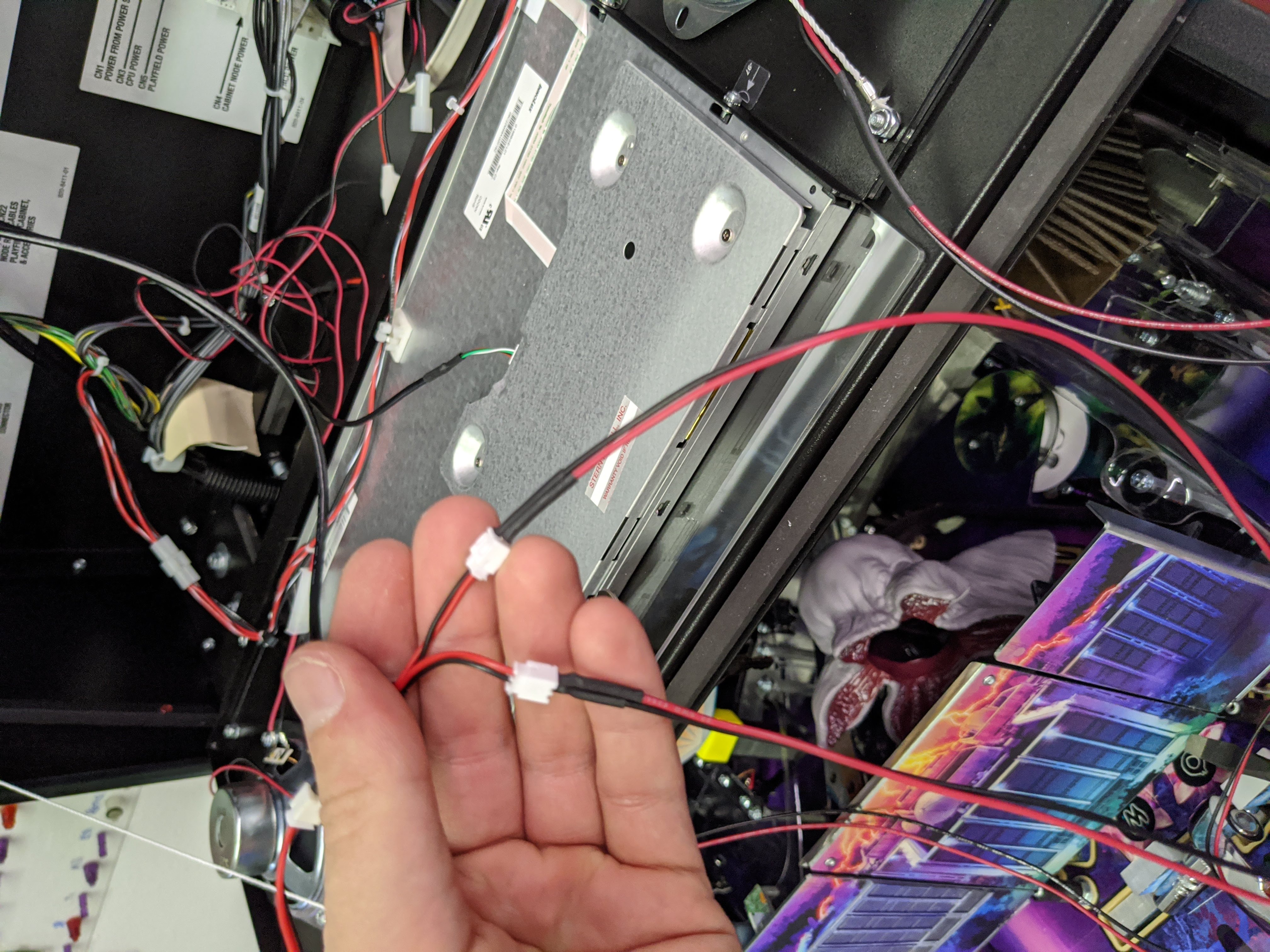
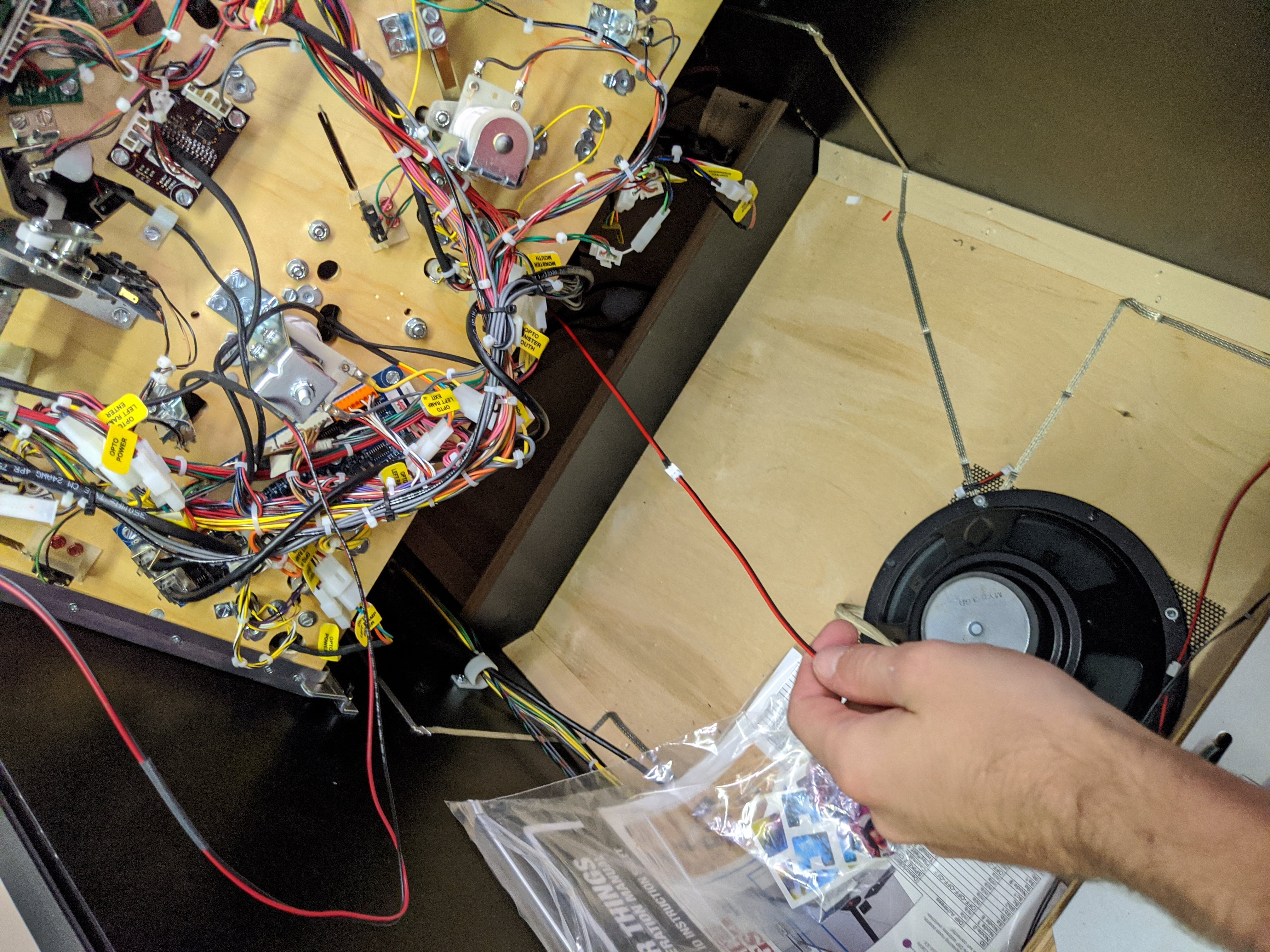
9. Attach the remaining included wire to the other side of the 2-way splitter and feed the wires through the hole on the bottom of the backbox so that it can be accessed under the playfield.
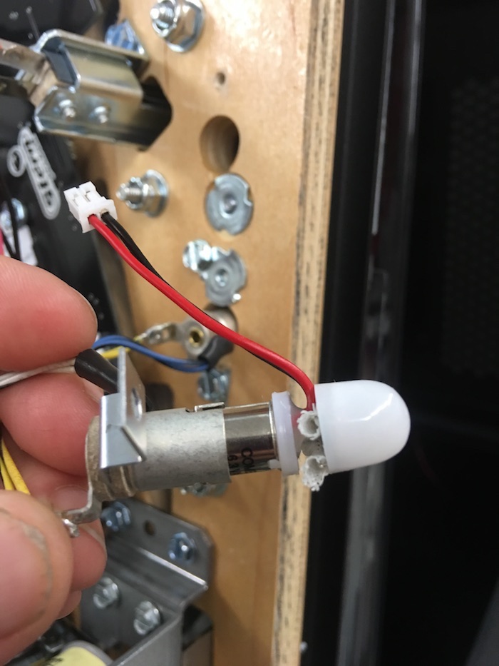
10. Locate a GI socket and remove using a hex driver. Remove the existing bulb by pushing in slightly while twisting and replace with the bulb provided. Push in and twist until it locks into place. You can also adjust the height of the bulbs dome so that it is closer to the top of the bayonet. Reattach the bayonet to the bottom of the playfield.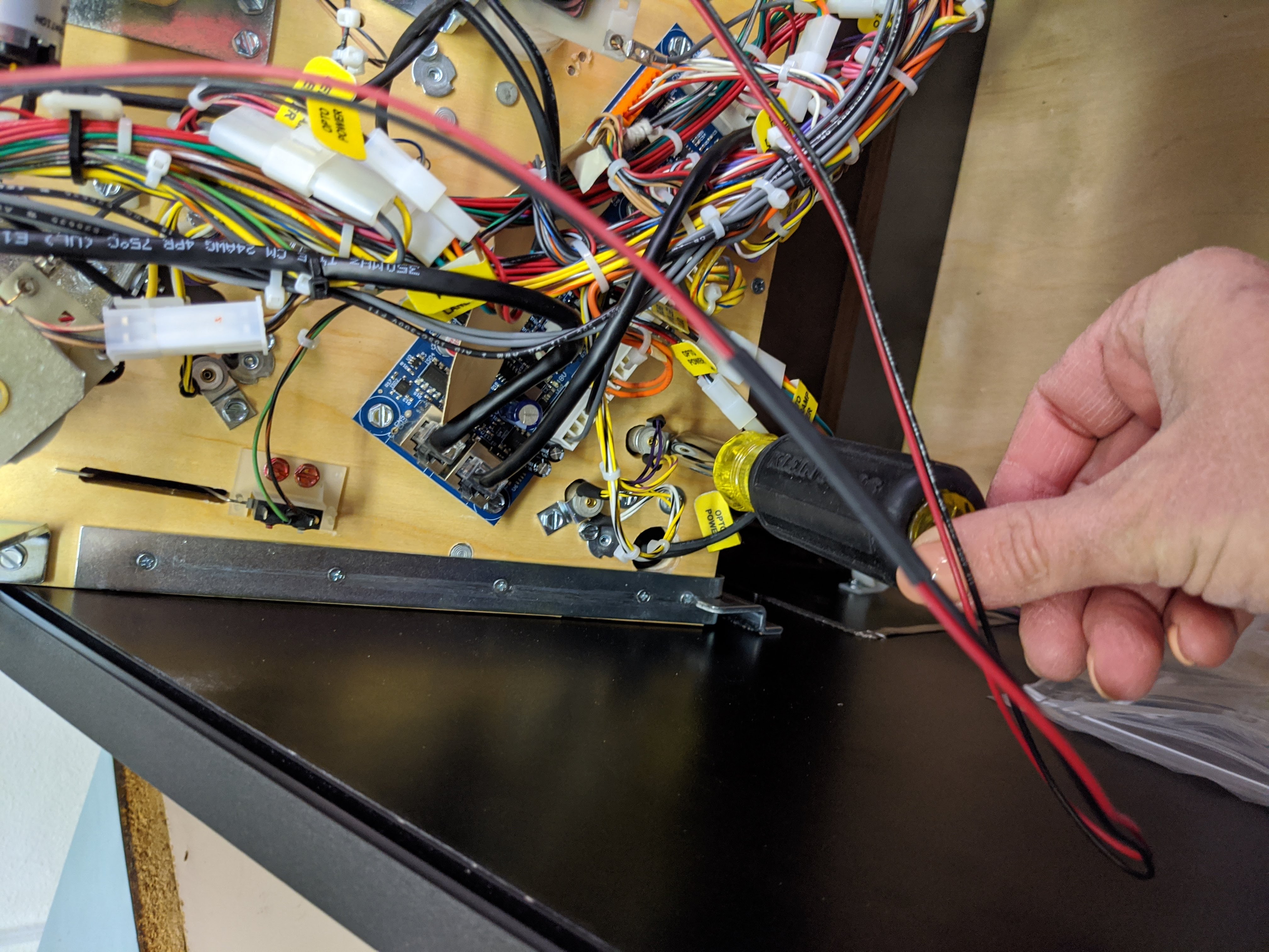
Lower the playfield and turn on your games power to test functionality. If some the lights do not function, please see this support article.
11. Replace the playfield and close the backbox. Remove the backing from the tape on the standoffs of the ABC panels.
12. Align the taped sections with the corners of the speaker panel mesh.
13. Complete!
Comments
0 comments
Please sign in to leave a comment.