
DANGER ELECTRICAL SHOCK
Pinball machines have high voltages which can cause DANGER TO LIFE AND LIMB. TURN POWER OFF and UNPLUG PINBALL MACHINE prior to installation. Pinball machines are high voltage and can cause electrical shock.
SAFETY GLASSES are also recommended while working with or installing pinball parts.
Please follow these safety instructions as well as all installation instructions. Failure to follow these instructions may result in damage to the pinball machine, accessory or other parts. Please see our Disclaimer for associated risks and responsibilities (Section 13 in our Terms of Service) prior to installation.
Images included in these instructions are of an installed prototype and may vary from your product slightly.
If you have questions or concerns regarding the proper installation of this part, please contact us for assistance.
When removing screws from the playfield, reinstall by first turning them counter-clockwise to match the original groove in order to respect the integrity of the playfield wood.
- Turn off game, remove glass and secure balls. Disconnect the hammer from the wire harness at the white connector near the hammer head.
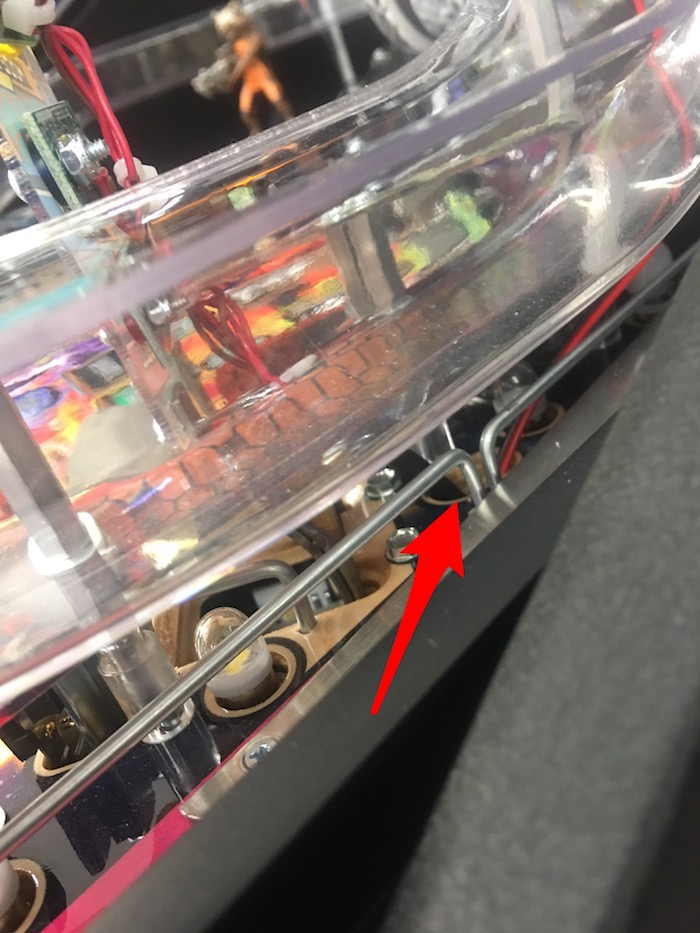
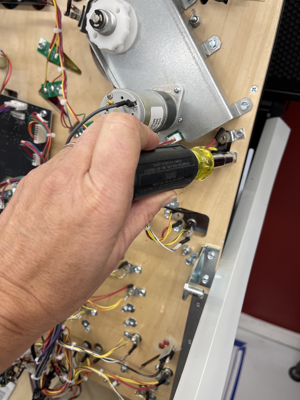
- Remove the screw holding the ramp and hex post on the right ramp, near the right orbit. Carefully attach the hammer by screwing into the hex post being careful not to over tighten.
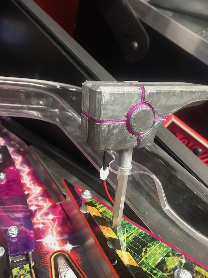
- Lift the playfield and run the wire harness up through the playfield using the hole under the ramp plastic. The hole is to the right of the scoop hole. Lift the playfield and run the wiring under the ramp and back up to the hammer. Reconnect the white connector near the hammer head.
- Lift the playfield to the upright position and locate a GI bulb socket below the area where the hammer is installed. GI bulbs are the always on domed LEDs found under the plastics on your playfield. They are attached using a socket from the underside of the playfield.
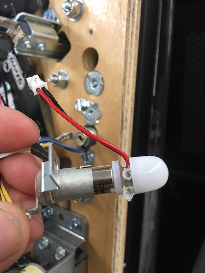
- Utilize a hex nut driver to remove the factory bulb. (Note: photo NOT of GOTG playfield; photo shows replacement bulb already installed).
- Remove the existing bulb by pushing in slightly while twisting and replace with the bulb provided. Push in and twist until it locks into place. You can also adjust the height of the bulbs dome so that it is closer to the top of the bayonet. Reattach the bayonet to the bottom of the playfield.
.
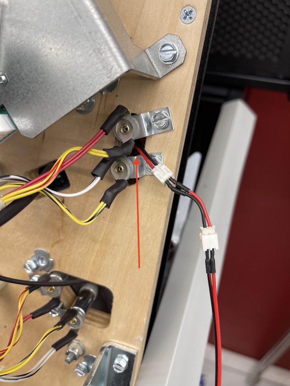
- Attach the wiring from the Interactive Lighting Kit to the replacement bulb wiring in the previous step.
- Attach the wiring from the Interactive Lighting board to the replacement bulb wire in the previous step.
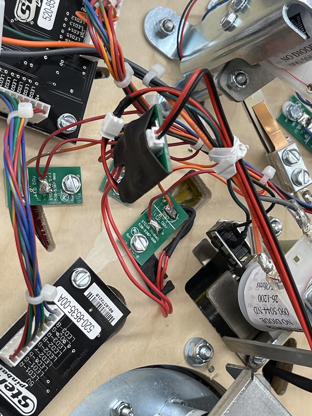
- Locate the desired trigger for the Hammer (magnet insert, for example). If the trigger light has an LED board, mount the light sensor bracket under the LED board as shown in the photo. If no LED board is available, utilize the tape provided to attach the light sensor bracket to the playfield near the insert.
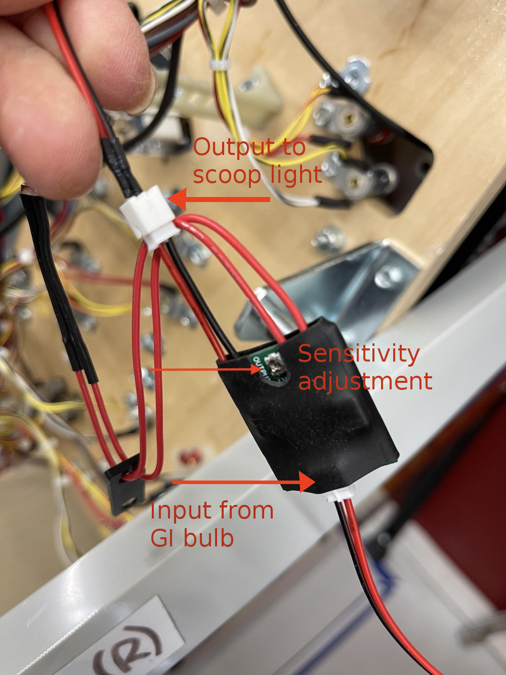
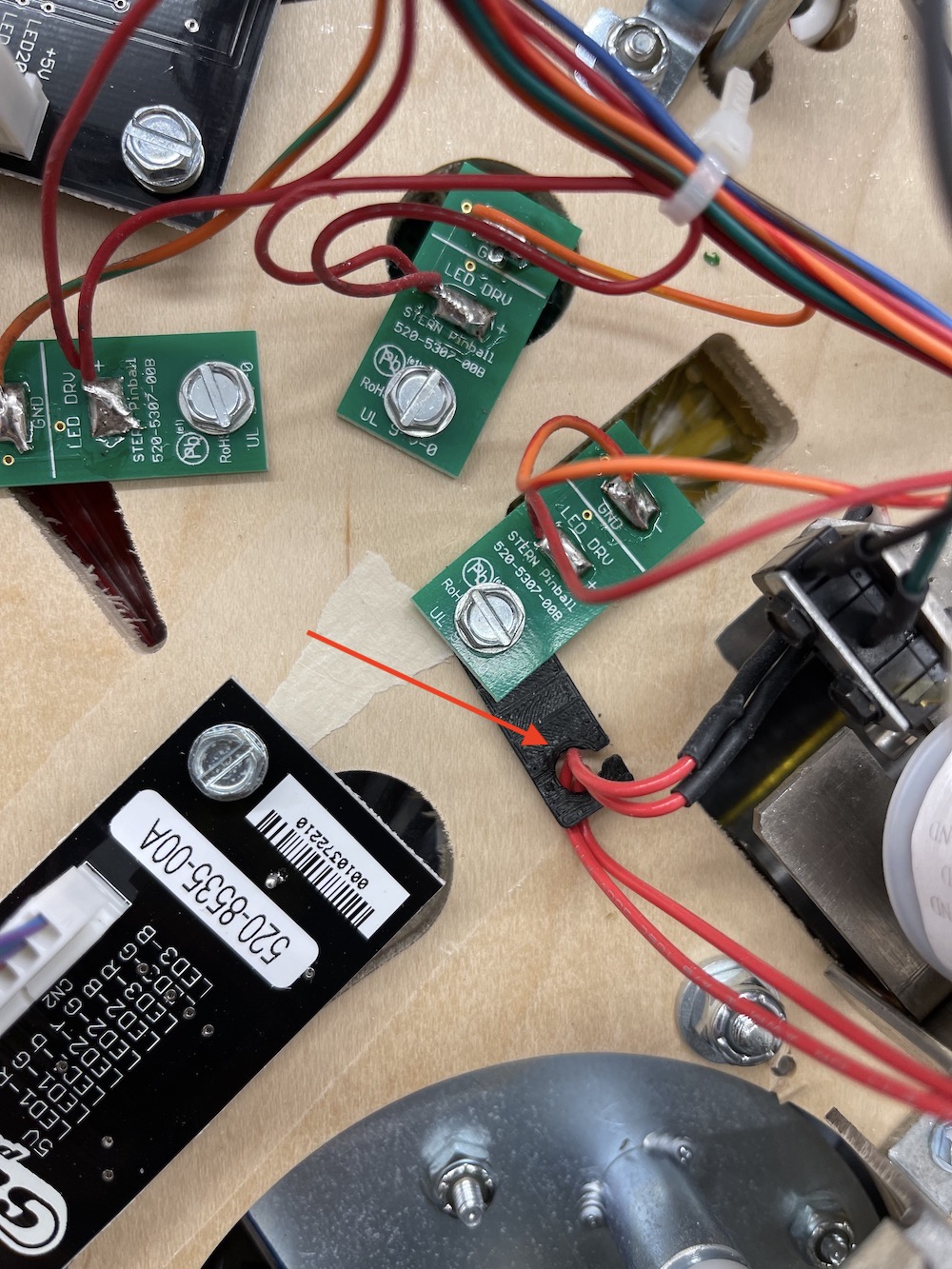
- Slide the light sensor wiring through the bracket for next step. Plug the wiring from the GI bulb (step 7) and from the Hammer (step 3) into the Light Sensor board. The Light Sensor board features a sensitivity adjustment (shown with arrow) to fine tune the triggering of the lighting feature. A small screw driver is required to make sensitivity adjustments. See below for details on making these adjustments.
- Attach the Light sensor bracket either under the trigger LED board (shown in photo) or attach to bottom of playfield; Be sure to leave enough slack in the light sensor wiring to put the light sensor under the trigger light.
- Next, position the light sensor so that it is pointing toward the LED inside the insert. The more the sensor is blocked by the LED board from other lighting, the better.
- Tidy up the wiring along other wiring in the game. Please note you will likely have longer wiring than is required for your particular installation.
- Lower the playfield and turn on your game to test the features functionality. Open the Diagnostics menu and navigate to LED test. Use the flipper buttons to navigate to the appropriate trigger light. Ensure that the hammer is illuminating with the trigger light.
Light Sensitivity Adjustments
Once the ILS board is installed you may find that the output light may have some ghosting (slightly lit at all times) or that it isn't lighting bright enough. This is where the sensitivity adjustment comes into play.
Take great care when adjusting the ILS sensitivity screw, it is a small delicate item. It is best to do these adjustments with the power off for safety. Turning the adjustment clockwise will make the sensor less sensitive to light, and counter-clockwise more sensitive to light. If the output light is staying lit when the signal LED is off (ghosting), turn the adjustment a hair clockwise and test again, repeat until the desired effect is achieved. This may result in a slightly dimmer output light if over
adjusted.
The goal is to have as bright a light as possible without any ghosting.If the output light is too dim, turn the adjustment counter-clockwise a hair and re-test, repeat until the controlled
light is bright, and has no ghosting.
Comments
0 comments
Please sign in to leave a comment.