

DANGER ELECTRICAL SHOCK
Pinball machines have high voltages which can cause DANGER TO LIFE AND LIMB. TURN POWER OFF and UNPLUG PINBALL MACHINE prior to installation. Pinball machines are high voltage and can cause electrical shock.
SAFETY GLASSES are also recommended while working with or installing pinball parts.
Please follow these safety instructions as well as all installation instructions. Failure to follow these instructions may result in damage to the pinball machine, accessory or other parts. Please see our Disclaimer for associated risks and responsibilities (Section 13 in our Terms of Service) prior to installation.
Images included in these instructions are of an installed prototype and may vary from your product slightly.
If you have questions or concerns regarding the proper installation of this part, please contact us for assistance.
When removing screws from the playfield, reinstall by first turning them counter-clockwise to match the original groove in order to respect the integrity of the playfield wood.
NOTE: For this installation, we've chosen not to remove the stock acrylics before installing - but we've done this installation/removal on our game so many times that we are comfortable performing the installation while the stock acrylics are still in the game. However - if you feel that it would be easier to remove the acrylics, there is one screw holding each acrylic onto the playfield. BE WARNED however that re installation of the acrylics is a headache. This installation process is not exactly a walk in the park - so choose what you feel is the easier of the two methods (we think keeping them on the game).
- Twist together (unfray) the tips of the electric fence wires and disconnect the matrix splitter (included with kit) from both of the fence sides.
This is to make the rest of the installation process easier. You can untwist the wires to give that broken appearance after the installation is complete.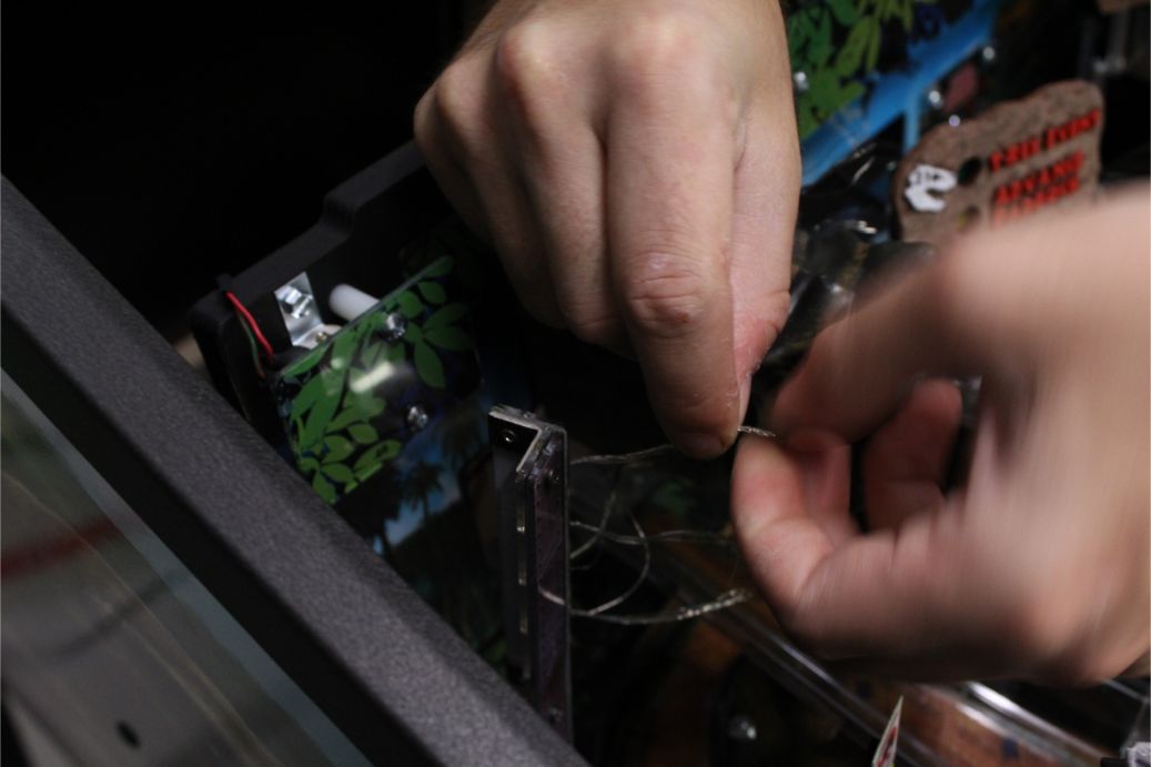
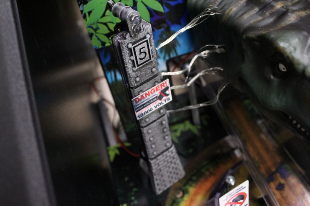
- Slide the left side electric fence cover over the twisted wires.
We find it best to carefully slip each wire into its corresponding hole one by one until all of them are inserted. You can see now why we recommended twisting the wire tips together first. Notice that we have NOT removed the tape backing yet.
NOTE: you may find a variation in the wire crimps closest to the fence uprights causing making fit difficult; if you encounter this issue, use a hand drill to widen the openings slightly.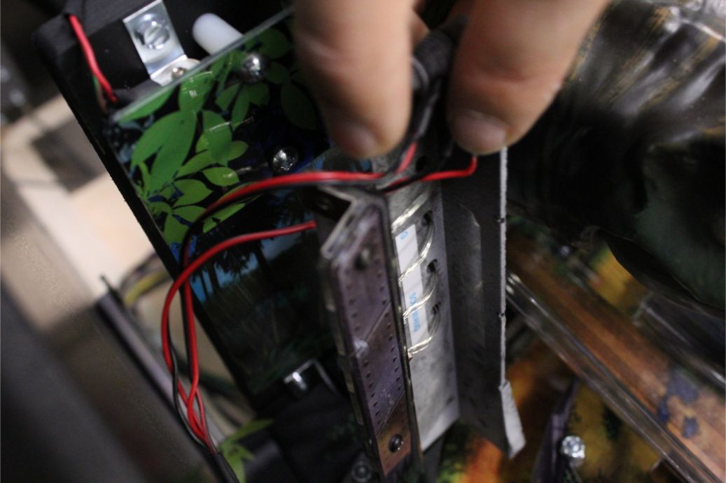
- Remove the tape backing from each of the tape pieces and work the fence cover onto the acrylics. Removing the tape is a delicate process, but after it is complete you can carefully work the fence cover over the acrylic. We found it best to slide the playfield out of the cabinet for easier access. Another tip is to pull all of the fence wires through as far as they can while attempting to slip the metal rivet looking things through the cover holes.
- Using Included wire clip, affix the lighting wires to the back of the acrylics so that the wires are concealed appropriately.
- Repeat this process for the left side fence post cover.
- Feed the right fence post lighting wire through the ramp cutout in the rear of the playfield.
- Using the included matrix splitter, attach the two lighting wires together.
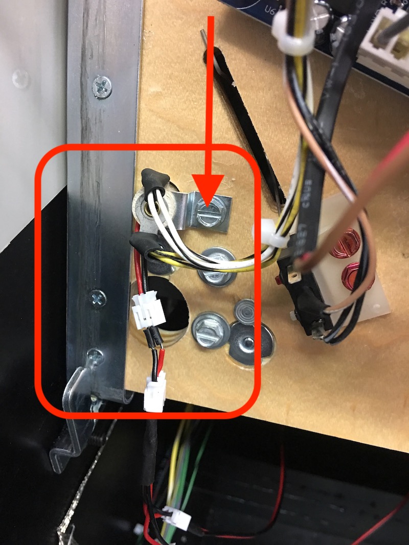
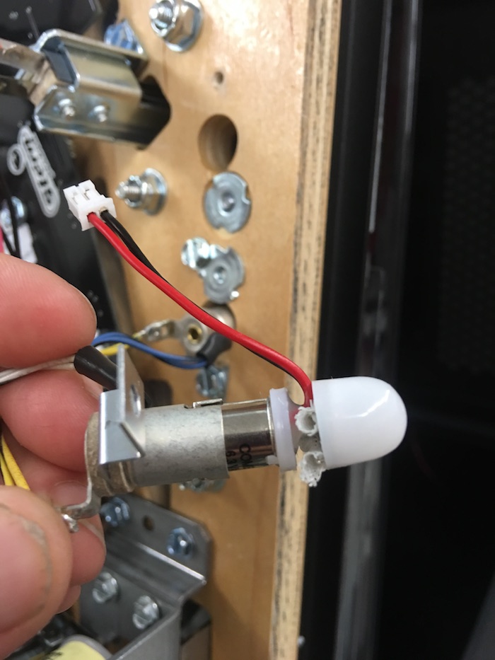
- Lift playfield into a standing position and locate the lower most GI socket. Remove the socket using a hex driver on screw (shown) then remove the bulb by twisting the factory bulb while pushing down to remove. Replace the bulb with the Frosted replacement, adjusting the frosted dome so that it is close to the top of the bayonet (shown in second photo).
- Next, remove the factory bulb by pushing down and twisting. Replace the bulb with the one provided with the product and push down and twist to secure. Push the frosted dome down on the bulb so it is closer to the base of the LED. Reattach the GI socket. If desired, you can utilize the alligator clips (included) instead of replacing this bulb.
9. If either one of your fence posts is not lighting up - use the included polarity swapper (small 1/2" matrix wire looking piece) between matrix splitter and the corresponding post that is not lighting up.
Comments
0 comments
Please sign in to leave a comment.