
DANGER ELECTRICAL SHOCK
Pinball machines have high voltages which can cause DANGER TO LIFE AND LIMB. TURN POWER OFF and UNPLUG PINBALL MACHINE prior to installation. Pinball machines are high voltage and can cause electrical shock.
SAFETY GLASSES are also recommended while working with or installing pinball parts.
Please follow these safety instructions as well as all installation instructions. Failure to follow these instructions may result in damage to the pinball machine, accessory, or other parts. Please see our Disclaimer for associated risks and responsibilities (Section 13 in our Terms of Service) prior to installation.
Images included in these instructions are of an installed prototype and may vary from your product slightly.
If you have questions or concerns regarding the proper installation of this part, please contact us for assistance.
When removing screws from the playfield, reinstall them by first turning them counter-clockwise to match the original groove in order to respect the integrity of the playfield wood.

Hardware Needed
- 1/4" wrench or socket
- 5/8" open-ended wrench
- Pinball Cabinet Assembly Protectors (Optional)
UNDER PLAYFIELD
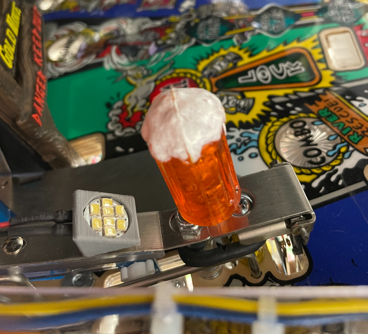
1. Install Light Mount
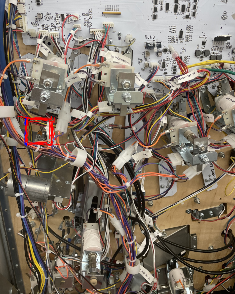
Install Light Mount with provided adhesive on ramp (use photo below for placement orientation). Connect male end of the 12" Matrix wire to 8SMD light and feed the female end through the opening indicated in reference photo below.
2. Install Spacer
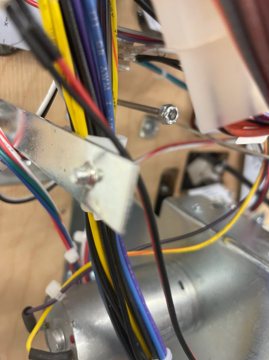
Open coin door and carefully remove glass. Place Pinball Cabinet Protectors on sides (optional). Lift playfield up and proceed to locate the following 1/4" nylon-hex nut. Remove nut, place spacer on rod, and reinstall the nylon-nut.
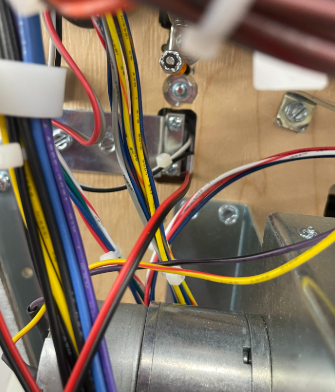
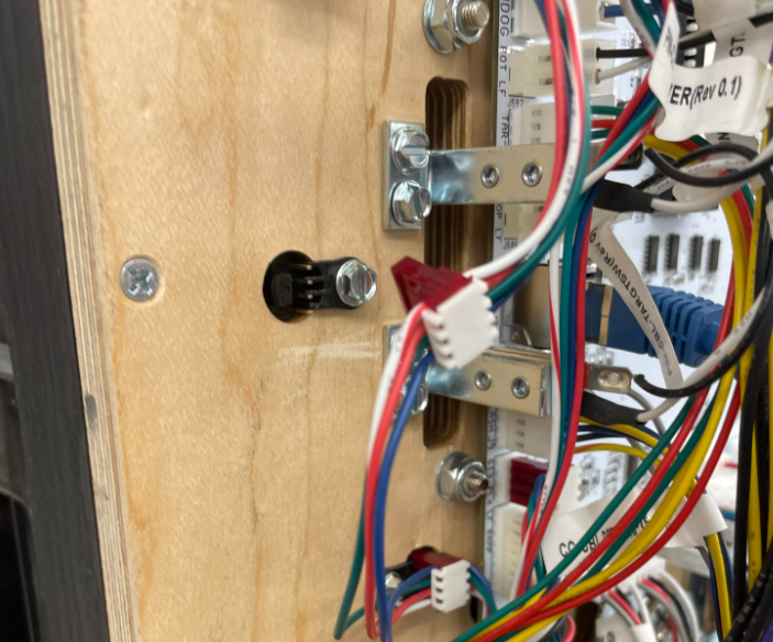
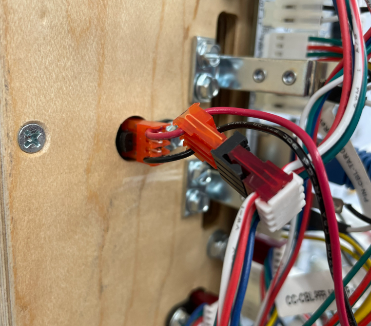
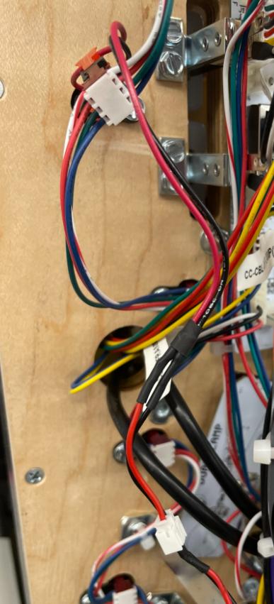
3. Install Backlight for Beer
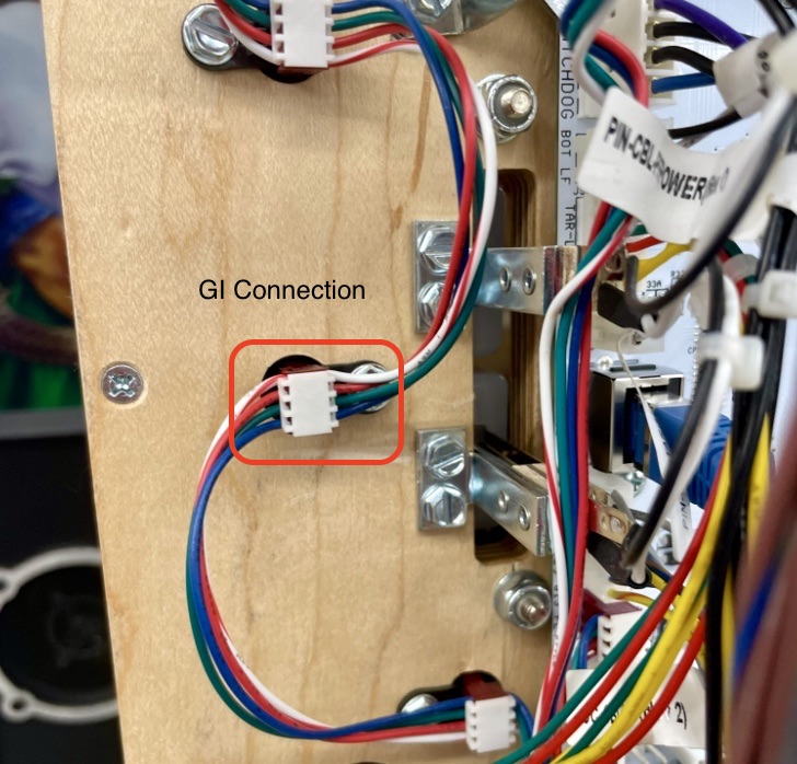
Locate a General illumination (GI) connection near where the wiring emerges from the playfield. Utilize a small flat head screw driver to pop the 4-pin connector out (there is a black tab that holds the connector in place. Plug the jumper connectors in (one to the GI, the other to the factory wiring harness. Once connected to power, connect female end of 12" Matrix to the 4-pin IDC assembly.
4. Lower Playfield and Continue Installation
PLAYFIELD
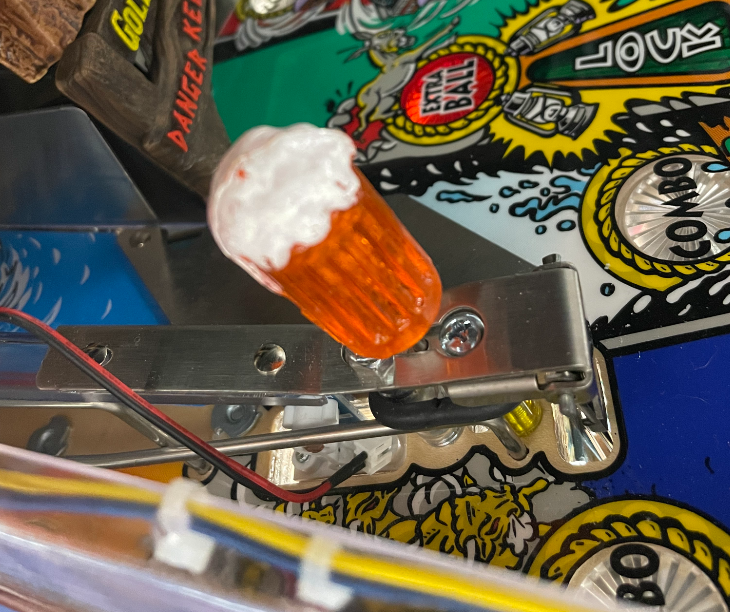
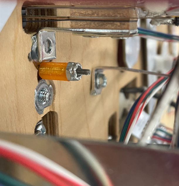
1. Slide Transparent Orange Mount On Beer Post
Using the slot on the Threaded Mount, slide the mount on rod. Slide existing white spacer into the thru-hole on the bottom of the Threaded Mount.
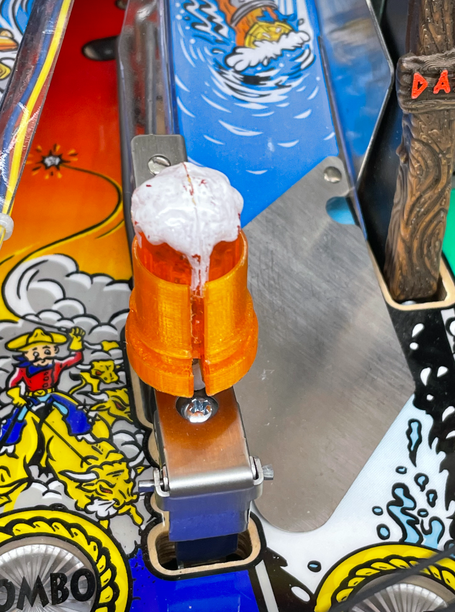
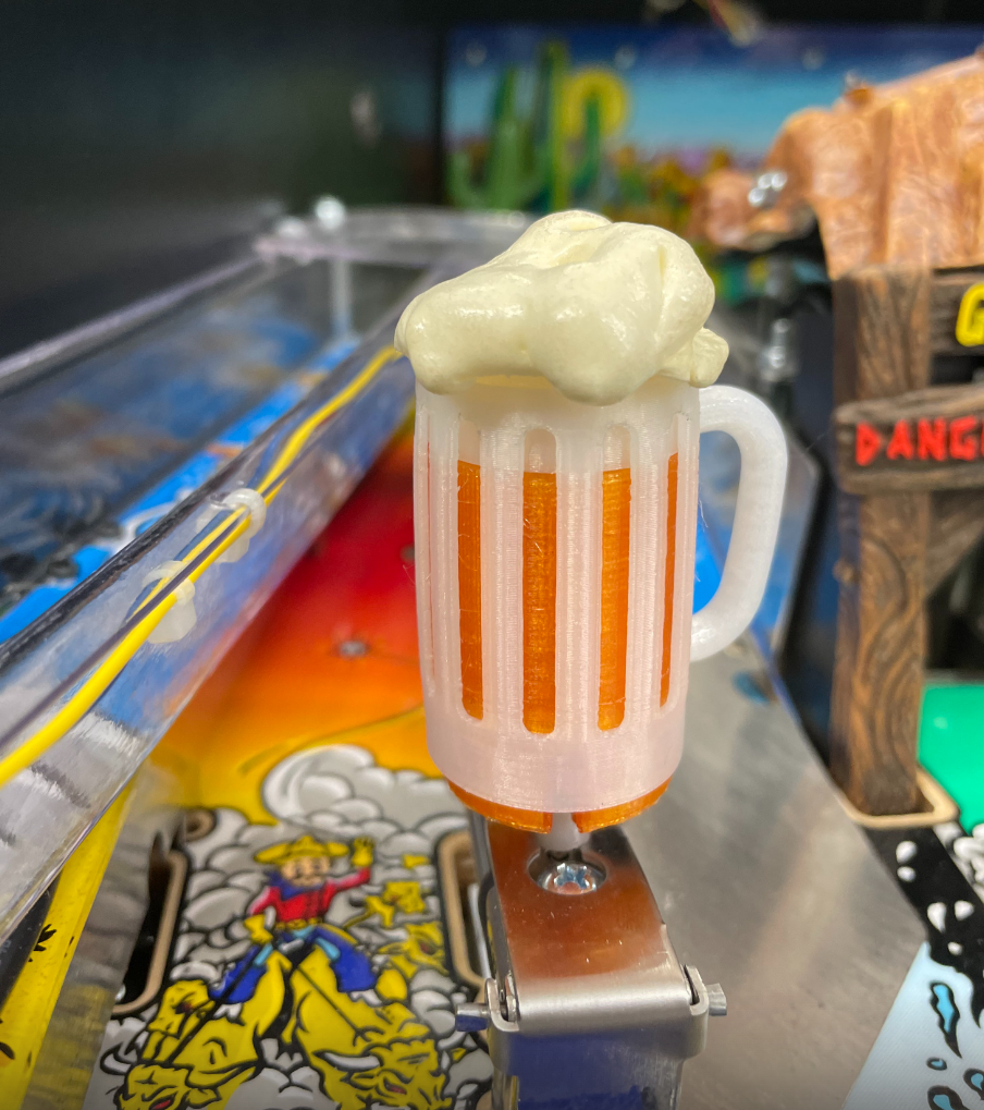
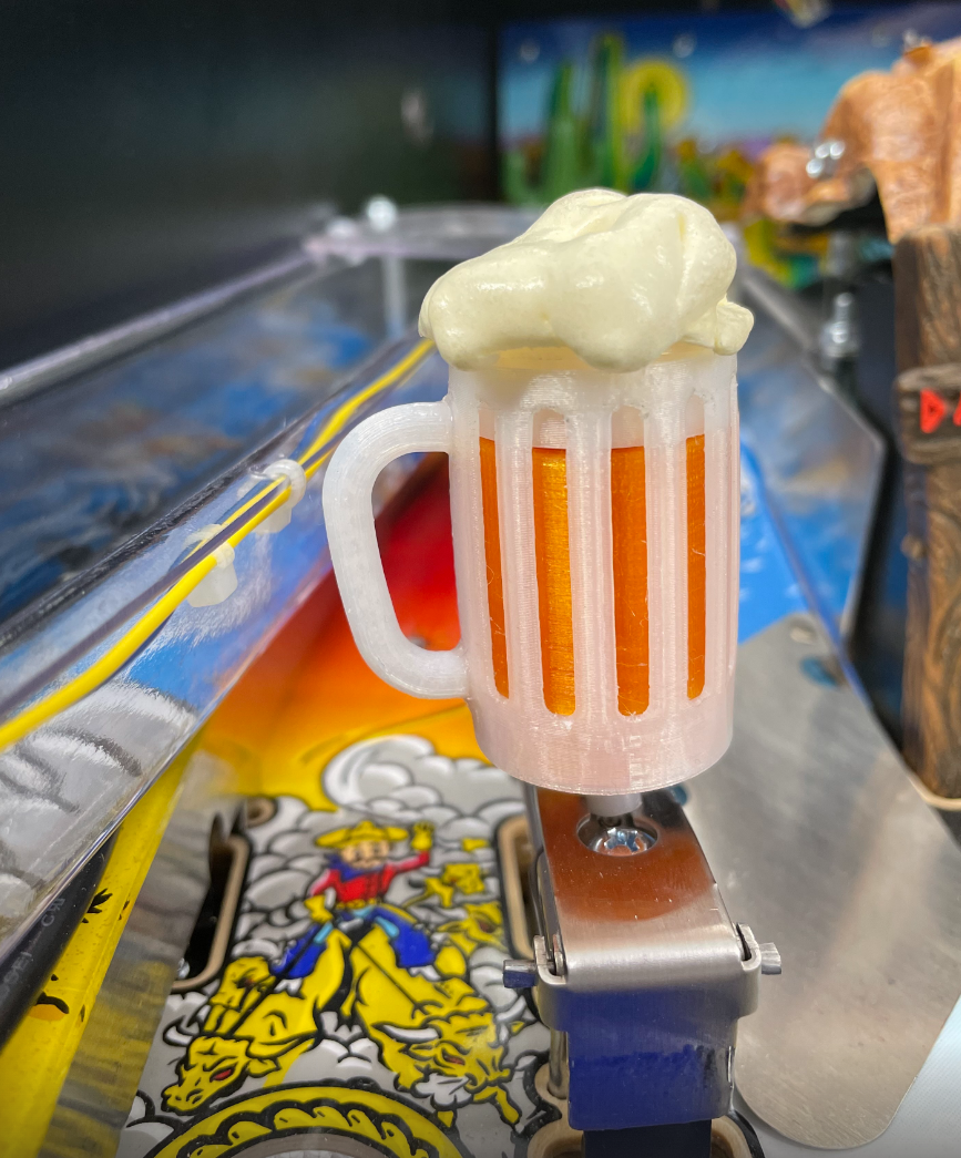
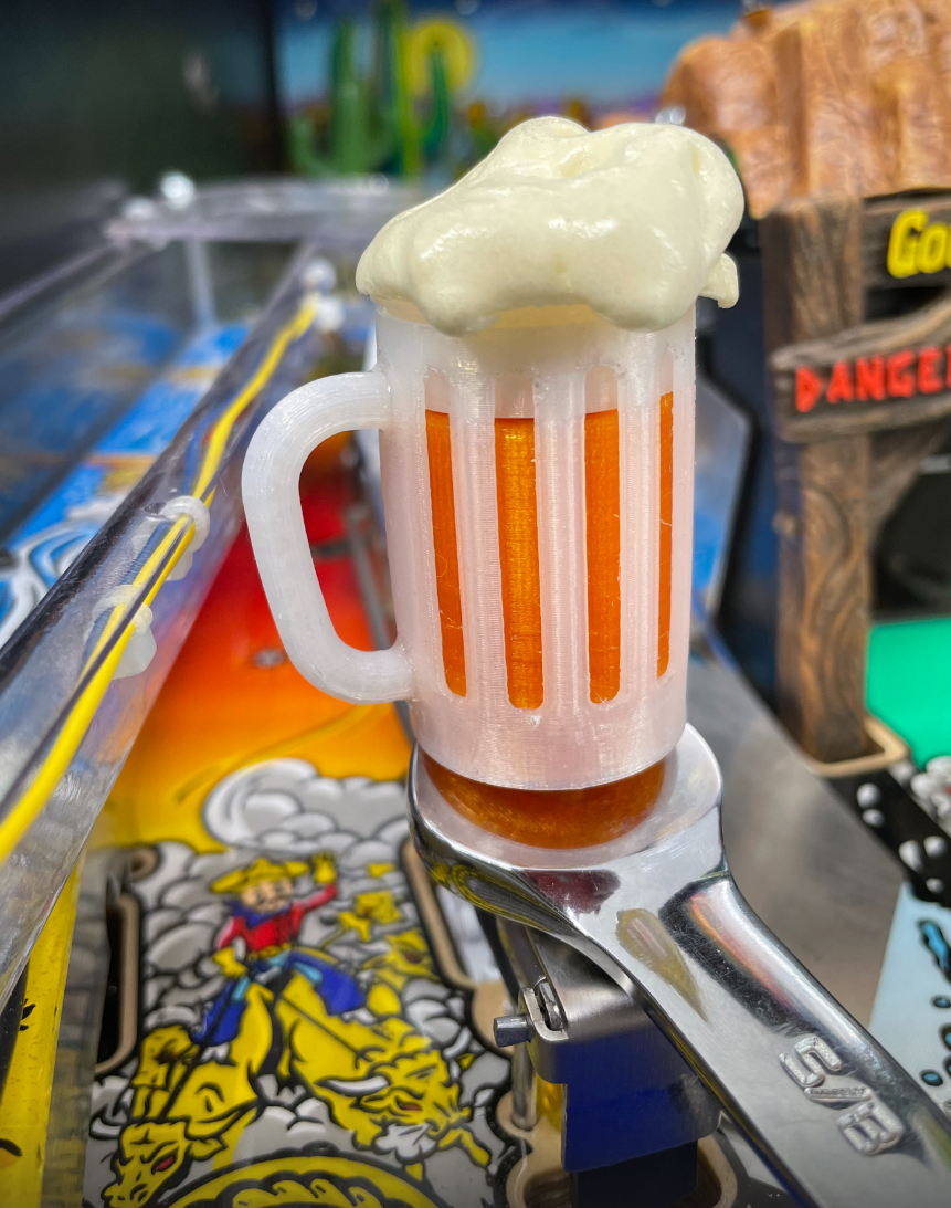
2. Slide Beer Upgrade over stock beer
Once Beer Upgrade is covering stock beer, begin threading in a clockwise position (assuming the installer is looking from top-down). Beer should rotate one and a quarter revolutions (450°) after initial engagement of threads. To verify this step was performed correctly. The bottom of the mount should be flush with the outer shell of the beer, as shown. Use a open-ended 5/8" wrench to tighten mount an additional 5°.
Comments
0 comments
Please sign in to leave a comment.